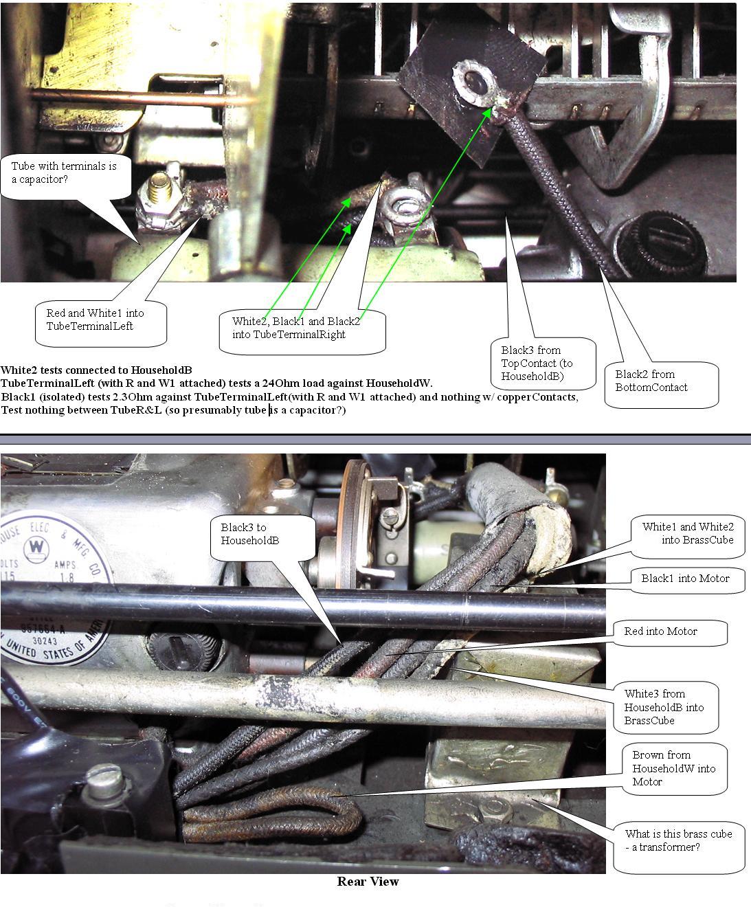
With no function keys pressed, I used an ohmeter to verify that the copper contacts are not touching, and that the wires connected to each contact are isolated from each other. The TopContact wire (Black3) connects directly to one of the male plug prongs (where the electrical cord plugs in) at the back. The BottomContact wire (Black2) connects to a screwterminal on a big capacitor (at least I assume this tube shaped thing is a capacitor) as shown in the photo; I disconnected this Black2 wire from the terminal to verify its continuity with the BottomContact and also its isolation from the TopContact and all that seems good.
As an experiment, I blocked the two copper contacts from touching (with a piece of electrical tape between them) and pressed the add function key with the result that this had no effect on the operation of the machine: as before the governor is spinning always and the 'add' operations proceeds with each button press.
Based on this, it seems the problem is coming from some place other than the copper contacts and their wires.
Friden Model C10 ElectroMechanical Calculator 1935
I isolated the White2 wire (which shares the same screwterminal as the BottomContact wire Black2) and oddly this has direct continuity with the TopContact wire (Black3). This would seem to make a short circuit (circumventing the copper contacts entirely) -- could that be the problem?
This White2 wire goes into a brass cube that I assume is a transformer?
Here's a poorly lit video showing a potential problem -- Should the motor's governor (flywheel) spin continously and spark like this? (The calculator seems to operate well otherwise.)
At the very end of the video (above), you can see the stepped drum make a turn as I press the 'Add' key one time.
Here's a photo taken from the rear of the machine with the cover off.
You can see the motor on the left and the wheel to the right
The follwoing photos show how the original plug and cord were replaced with a modern grounded 3-prong cord and plug.
The three photos above show how a standard modern 3 prong plug and cord were wired into the original 2 prong plug.
The bottom photo shows a standard detachable power cord (from any computer etc.) inserted into the new plug.
You can buy these 3 prong plugs, but I removed this one from an old computer power supply I had lying around.
As you can see,I attached the grounding (green) wire to the Friden chassis, which should offer a bit of safety.
(Note that the two exposed screws seen in the bottom photos are not 'hot' - they simply attach the original plug to the chassis.)
Links:
A tribute to Carl Friden & his company
The Friden Web Site.
Yahoo Groups has an e-group (moderated) for Fridenites.
Here is a link with helpful Friden info, and which details - in German - How to remove the carriage on a newer model Friden.
Here is an English translation of the same site (courtesy of Google translate).
And below is a note (related to the above links) I received in September 2008 from Mark Glusker (thank you Mark):
I see you have a link to the Rechnerlexikon page on removing a Friden carriage. I created these images and a friend in Germany translated them into German for the Rechnerlexikon page. In case you are curious, here are my original captions in English:
Step 1 - remove the three levers from the carriage
Step 2 - underneath the carriage cover on each side there is a small lever that must be pushed upwards, then the cover can be removed
Step 3 - on a few machines, there is a small L-bracket at this location, towards the left end of the carriage (the machine in the photo does not have it)
Step 4 - loosen, but do not remove the screw at this location (for a close-up of this screw, see Step 5)
Step 5 - the red arrow shows the screw you just loosened, the blue arrow shows the direction to pull the small bracket that is now free
Step 6 - the long comb-like bracket can now be tilted up in the direction of the blue arrow (you may need pull the two levers indicated by the red arrows outwards and rotate the wheel indicated by the curved red arrow)
Step 7 - remove the bracket and spacer as shown
Step 8 - the carriage should now slide off the machine towards the right side (as viewed from the front of the machine)